This site is not affiliated with Track Time Performance. It is one customer’s documented account of work done by that shop in Houston, Texas, in 2026. The shop’s own site is tracktimeperformance.com.
All photographs in the first seven sections were taken by me on the dates noted; the last section was sent by the second shop. Click any photo for the full-size image.
First return, September 12
Taken in my driveway on September 12, 2026, within an hour of picking the car up.
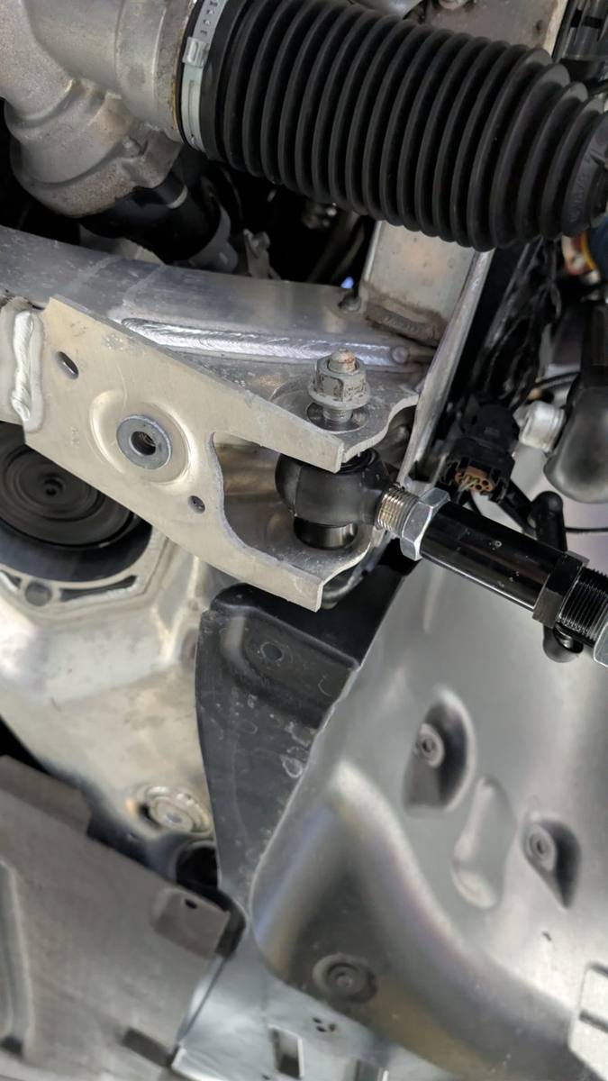
1. Driver's front caster arm at first return, sitting at an angle it cannot occupy when the subframe bolt is clamped. Bolt was completely loose.2. Driver's front FLCA-to-subframe bolt at first return. Nut never tightened.
Steering
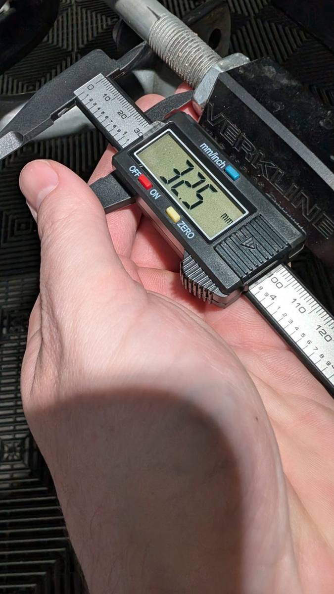
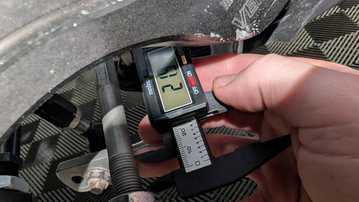
Measured with calipers, October 2–3. The second shop later traced the difference to unevenly set camber plates compensated at the arms and tie rods.
3. Driver's side tie rod adjuster thread exposure, 32.5 mm.4. Passenger side tie rod adjuster thread exposure, 21.9 mm. Difference 11.6 mm.
Caster arm damage
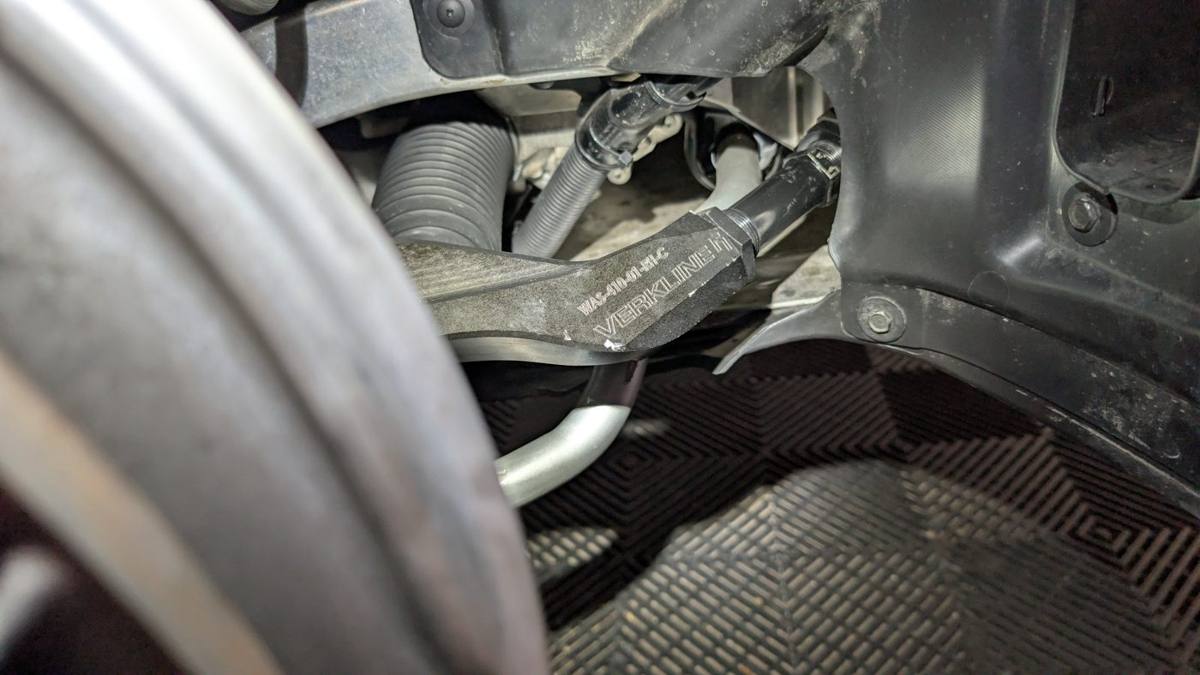
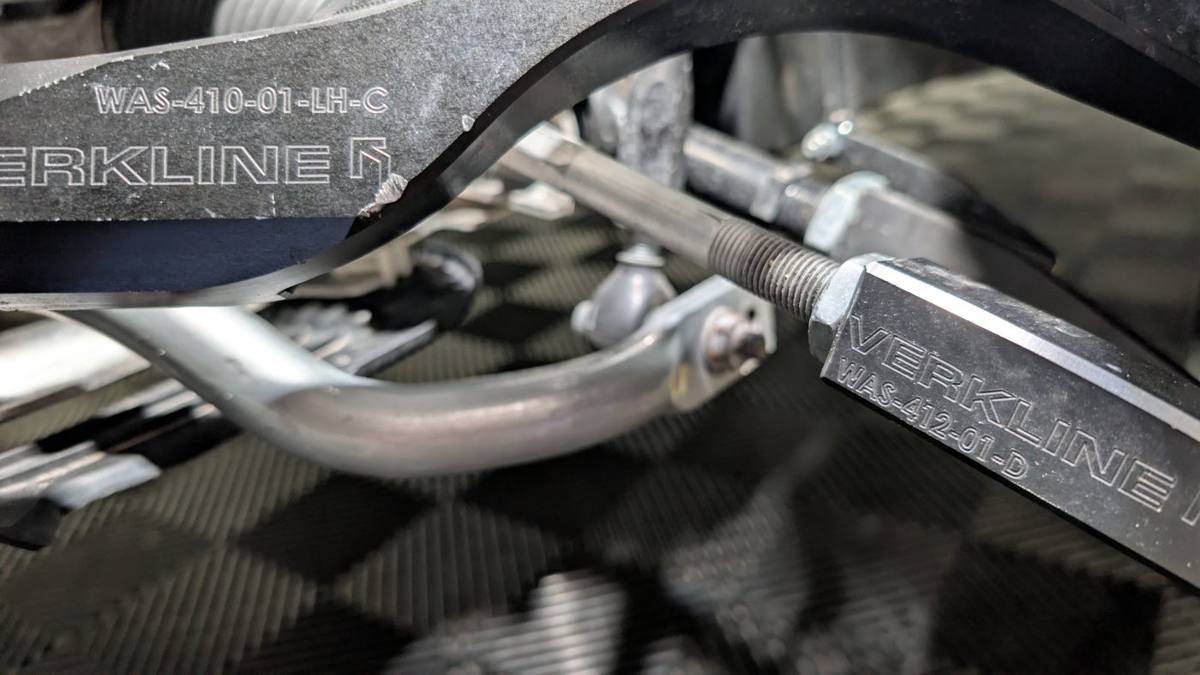
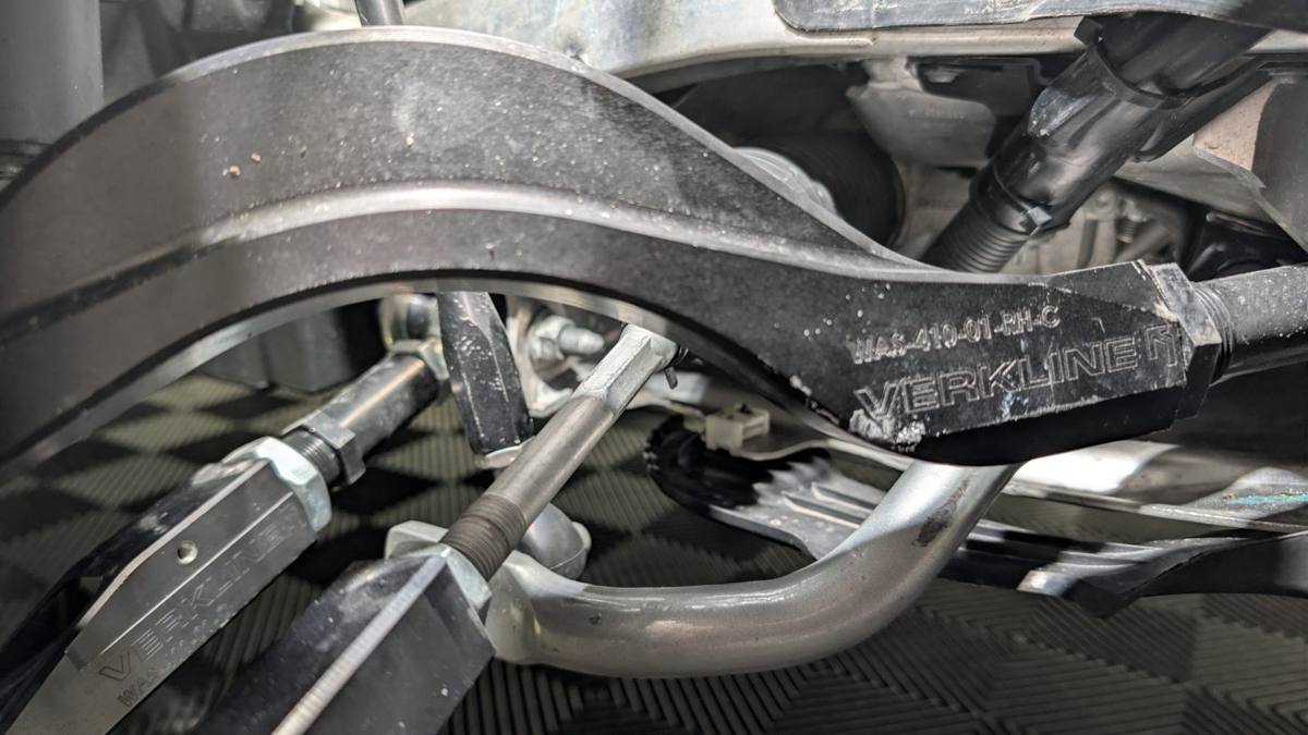
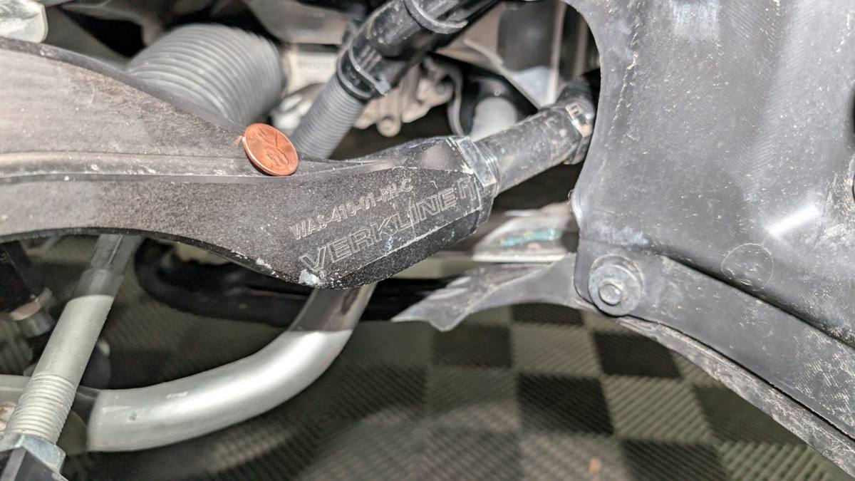
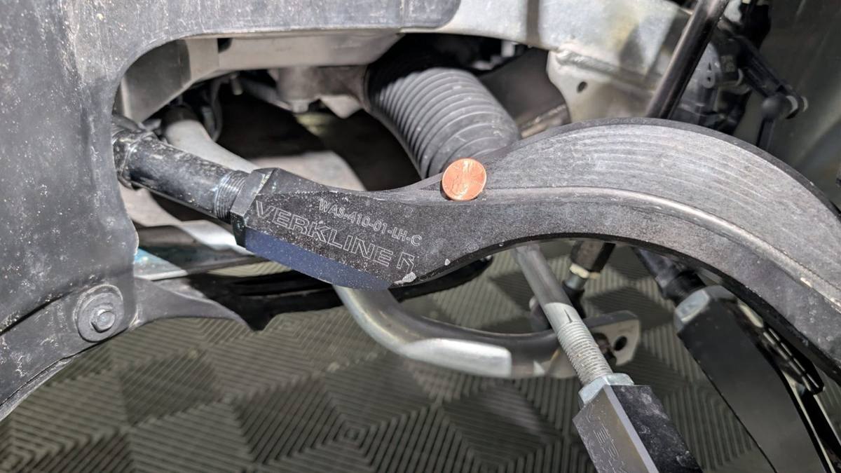
Both Verkline front caster arms, from the passenger front wheel contacting the arm at full lock. The passenger side is worse.
5. Driver's side (LH) caster arm WAS-410-01-LH-C with contact damage to the edge; tie rod adjuster (WAS-412-01) thread exposure visible for comparison.6. Passenger side (RH) caster arm WAS-410-01-RH-C with contact damage; tie rod thread exposure differs from the driver's side by 11.6 mm of arm length.7. Passenger side caster arm WAS-410-01-RH-C, contact damage with penny for scale. Heavier damage of the two sides.8. Driver's side caster arm WAS-410-01-LH-C, contact damage with penny for scale.
Wheel damage
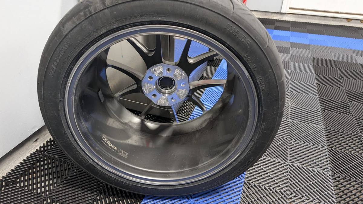
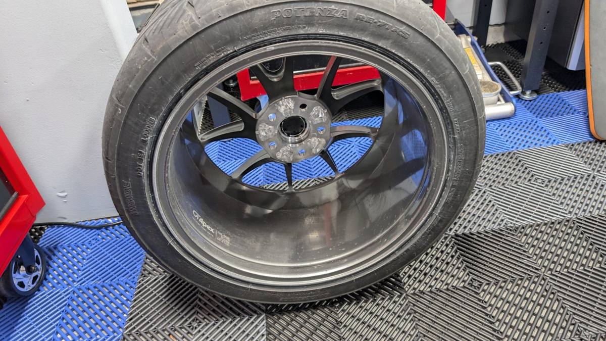
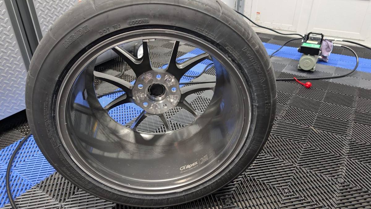
Three of four Apex VS-5RS wheels gouged at the inner mounting pad and spoke backs. The wheels had about 25 miles on them when the shop received them.
9. Damaged wheel 1 of 3: gouging into the metal at the inner mounting pad and spoke backs.10. Damaged wheel 2 of 3, same location.11. Damaged wheel 3 of 3, same location.
Ride height and spacers
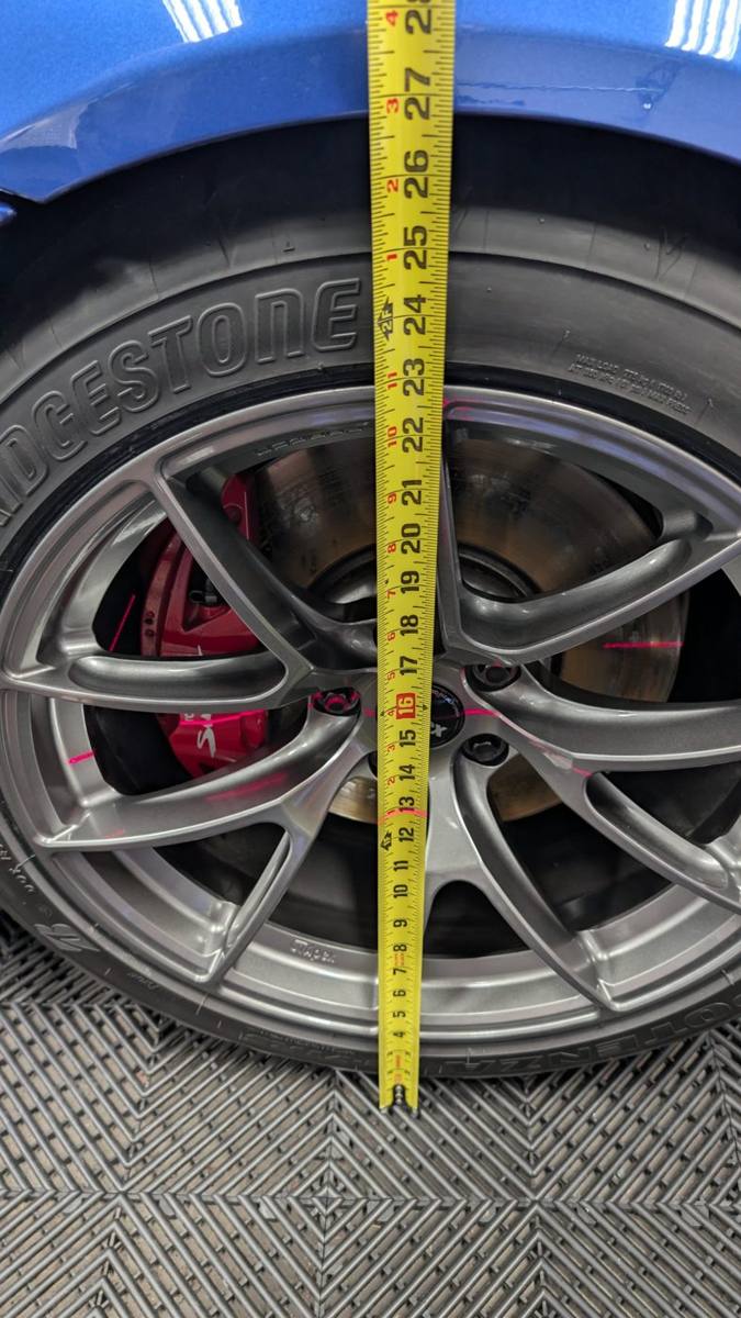
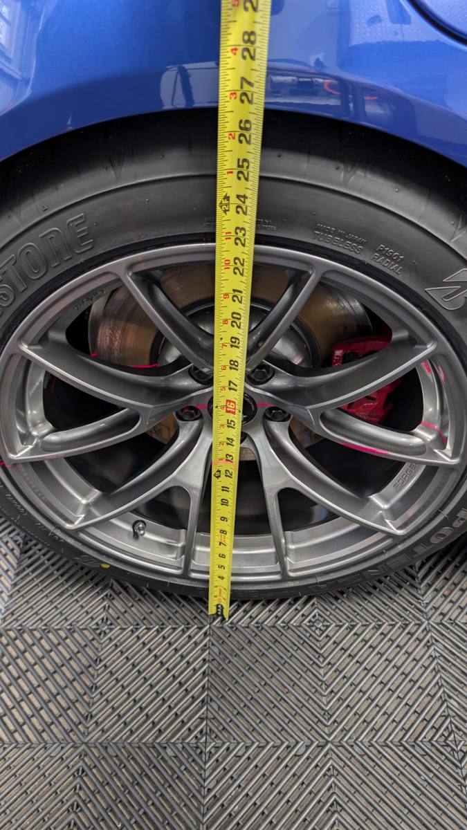
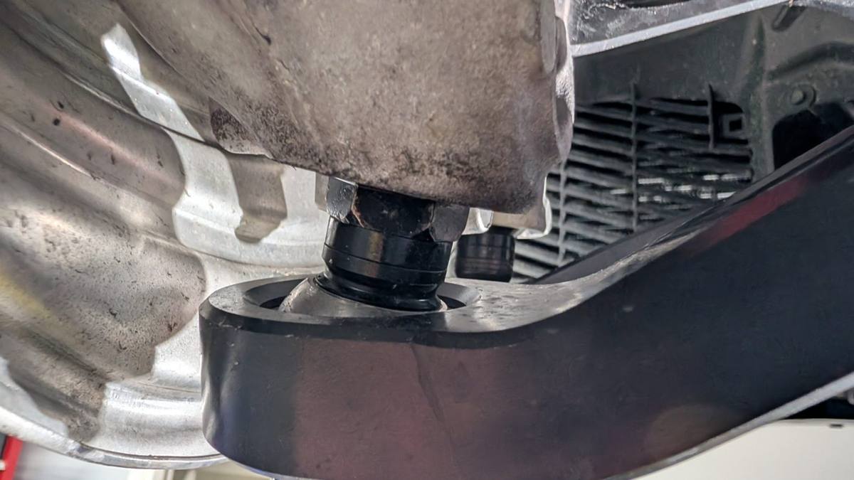
Hub-to-fender measurements showing reversed rake, and the mismatched roll center and bump steer spacer stack.
12. Front hub-to-fender measurement, laser line at hub center to fender lip.13. Rear hub-to-fender measurement, same method. Rear sits approx. 0.2 in. lower than the front; requested rake was 0.2 in. lower at the front.14. Front lower ball joint with roll center spacer stack (5 mm). Tie rod end carries 10 mm of bump steer spacer on the same corner; the two were not set from a measured curve.
Paint marking
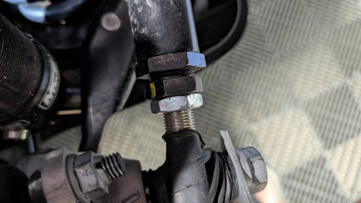
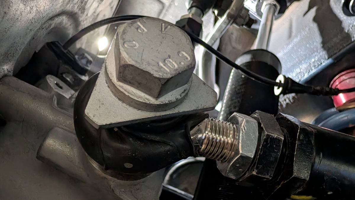
Marks were applied only to arm adjusters. No hub or subframe fastener was marked.
15. Paint marking as delivered: applied to an end link adjustment jam nut.16. Structural 10.9 mounting bolt with no paint mark. Marking was applied only to arm adjusters, never to the hub or subframe fasteners, which were the ones found loose.
Oil cooler
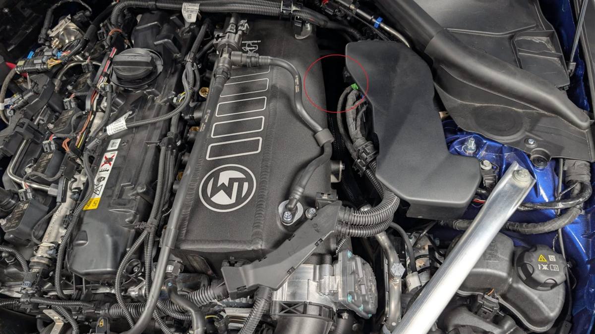
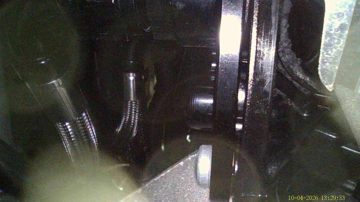
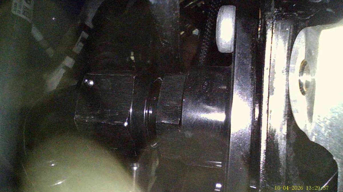
Borescope images of oil seepage at the distribution plate on the engine block, October 4.
17. Engine bay; the Verus oil cooler distribution plate sits below the circled area on the side of the block, out of direct view.18. Borescope image, Oct 4 2026: oil seepage at the Verus oil cooler distribution plate on the engine block.19. Borescope image, Oct 4 2026: second view of seepage at the distribution plate fasteners.
Second shop inspection, October 31, 2026
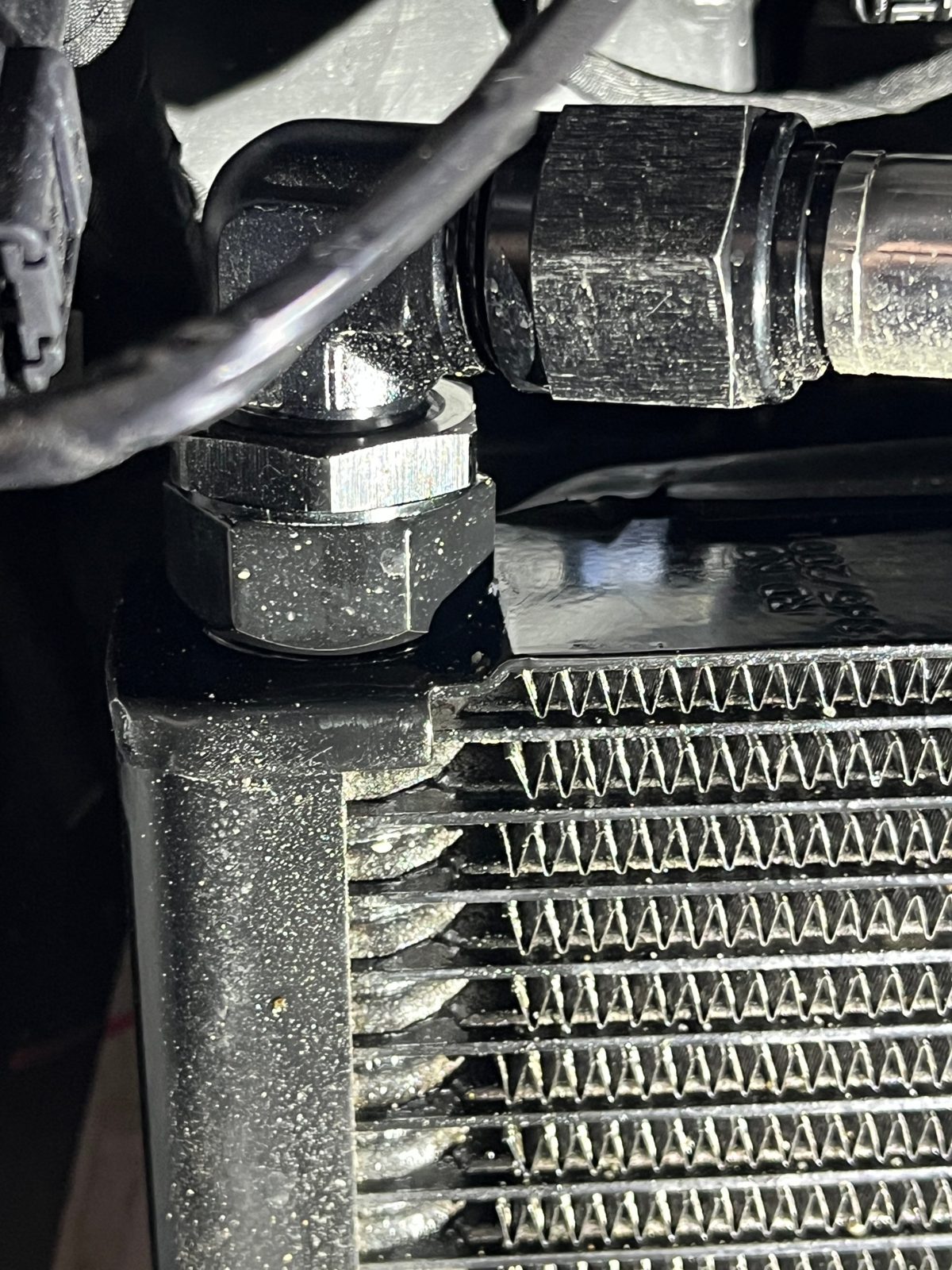
Photographs taken and sent to me by the second shop during teardown.
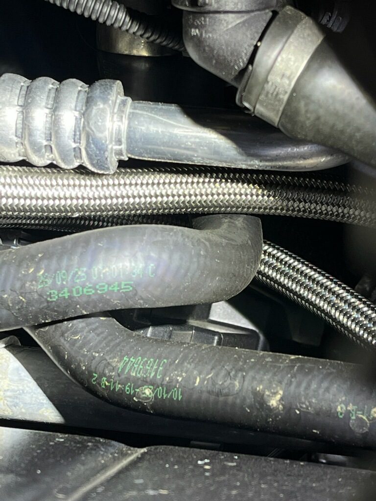
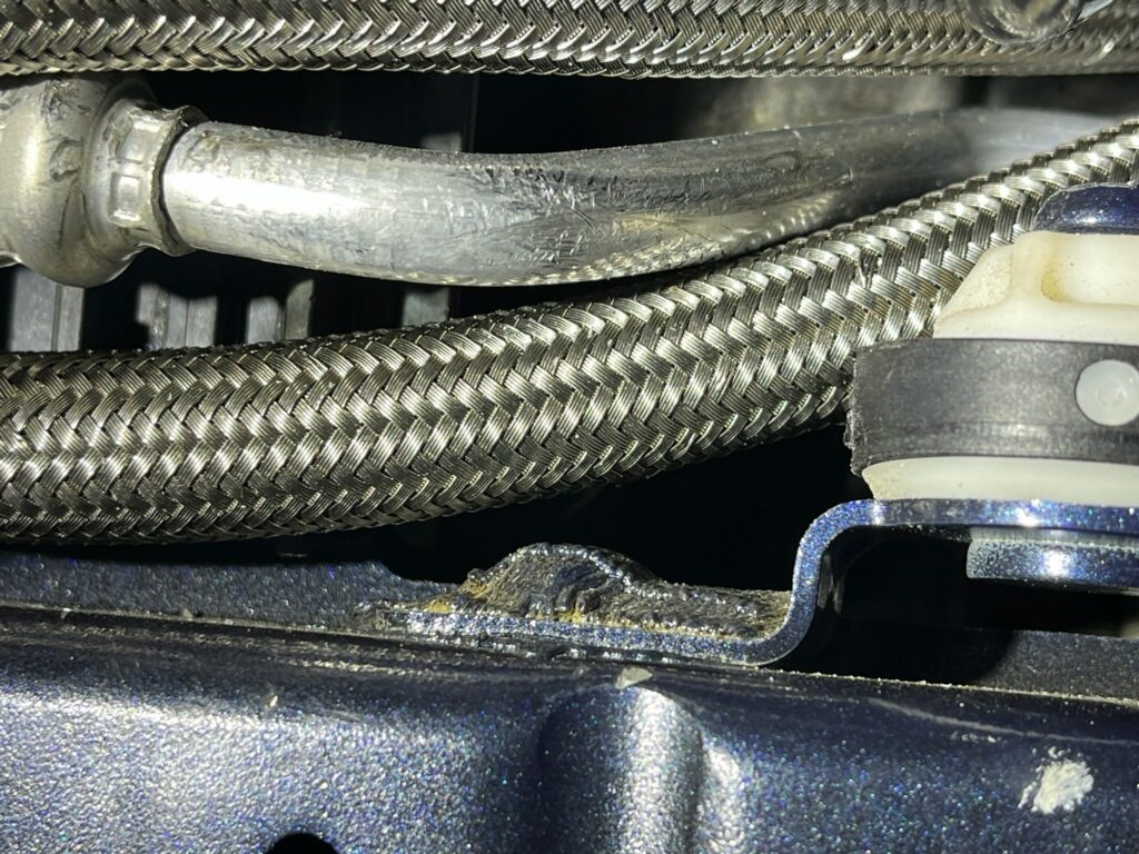
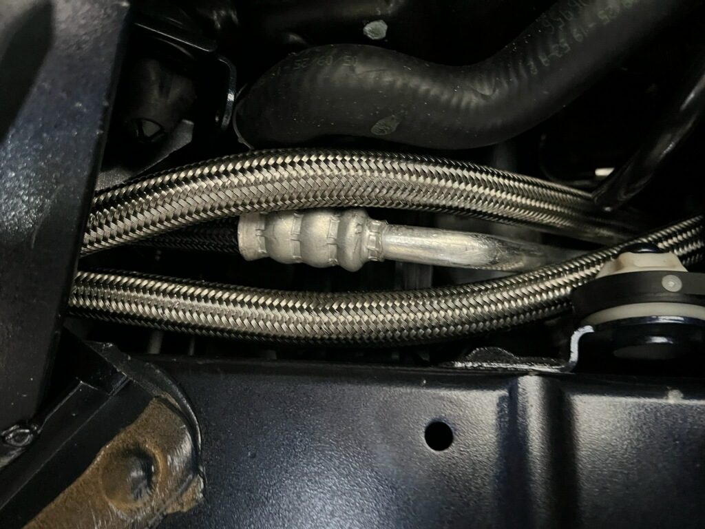
20. Oil residue at the fitting on the oil cooler end tank; the shop reports an active leak here.21. Braided oil cooler line routed in contact with a coolant hose and a crimped air conditioning line.22. Braided oil cooler line pressed against an aluminum line and a chassis bracket.23. Both oil cooler lines crossing an air conditioning line with no separation.